MAP RF v3RF site survey equipment |

|
|
MAP RF gives you the power to conduct detailed RF site surveys without the need to buy or hire expensive equipment. By utilising your existing RF receiver/radio MAP RF can be used to conduct a more realistic, real world RF site surveys more often and more cost effectively. This portable, compact unit is both powerful and affordable, just compare MAP RF to alternative approaches & products on the market. |
|
MAP RF monitors the received signal level indication voltage produced by many RF receivers. Position data is provided by a GPS built within the MAP RF Controller. These two sources of data are fed to a PC via a USB connection, which also provides the power to the MAP RF Controller. Software running on the PC processes the information and displays it in several ways including a colour coded plot and text listing. The data can also be exported so that it can be processed and displayed by third party software, eg MapInfo.
A MAP RF system consists of three main parts; a) the receiver, b) the controller and c) a laptop running the MAP RF software.
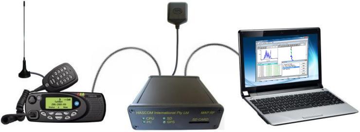
a) The receiver can be any device supplied by the user which produces a voltage level to show some signal level. This typically will be a two way radio or a wide band receiver but can also be connected to may other devices, such as a mobile phone, a fuel gauge or even an electronic altimeter. Voltage levels, by default, are expected to be between 0 - 5 vdc, but the controller can be configured for almost any voltage range.
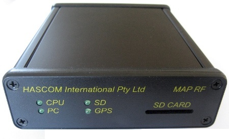
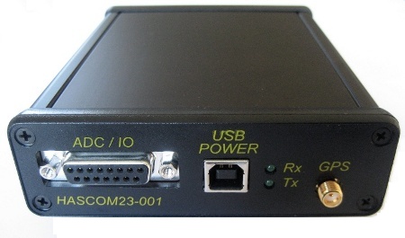
b) HASCOM's MAP RF Controller v3 is a microprocessor based unit which can take readings of voltage levels using analogue to digital converters (ADC's) from 4 sources simultaneously. It has a built in 65 channel, 20 Hz GPS to provide latitude and longitude position information. There is a USB port to transfer the data a PC or laptop computer. There is also an accessory port which provides additional RS232 serial support, which can, for instance, be used to control certain receivers. Raw measurements of signal level are taken several times a second and averaged to give a value for the second. The average signal level value and the position information are fed to the PC typically once per second.
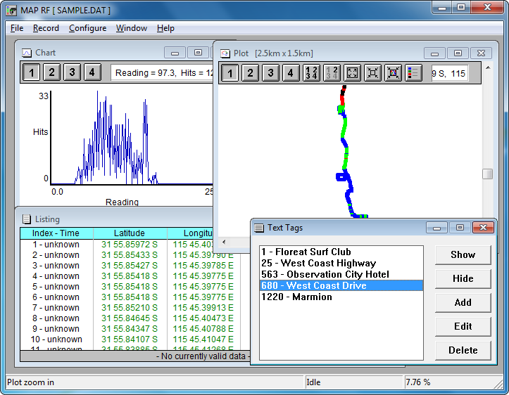
c) The MAP RF software provides control of the system, receives and stores all the measurement information from the controller. The measurements are calibrated by use of a calibrated signal generator and an easily defined calibration table to produce accurate readings in any units (eg dbm, mW, etc). The readings are displayed in several formats including a text listing, a trend chart and a colour coded plot. Any reading can have a text tag attached to it to help define the reading. The information can be exported in to a text file in several formats (eg for import into a spread sheet). The colour coded plot can be printed to fill a page or scaled and printed on a transparency for overlay on a map.
The improved specifications of the new v3 hardware include:
- Much faster CPU, able to do more powerful real time processing of data
- 4 x 10 bit analogue to digital (ADC) inputs with a much higher sample rate
- GPS with 65 channel architecture, 20 Hz update rate, 2.5m accuracy and 29s cold start
- USB connectivity for power and/or data connection to a PC
- SD memory card support for stand alone data logging
- Auxiliary serial RS232 port and I/O lines for control & monitoring of external equipment.
- Buzzer for configurable audio feedback
At this stage the v3 software is not yet available. However, the MAP RF v3 hardware is supplied with firmware that is compatible with the v2 software. This allows the hardware to be used now, but rest assured when the v3 software is available your unit will be freely and easily upgradable. For more information on v2, see the MAP RF v2 page.
MAP RF software features:
- The signal strength reading from up to four receivers is automatically measured several times a second and averaged over the second.
- Position information is provided by a 65 channel, 20 Hz GPS every second.
- Information is gathered by a simple 32 bit Linux application and displayed in three powerful ways; a text listing, a trend chart and a colour coded plot.
- Readings can be taken at an interval of 1 second or up to several hours, or by distance since the last reading.
- Full calibration of each individual receiver is easily accomplished with a known variable signal source to provide actual units, ie dbm or mW.
- Data automatically written to disk in case of power failure during recording.
- Ability to filter invalid readings, for example when the GPS was not tracking.
- Results can be printed as a text listing, plotted on transparency for overlay on a map or saved to a text file for import into other software, such as a spreadsheet.
- Full online help is provided for the software and hardware.
- Readings can have a text tags associated with them.
Some of the new features we have planned for the v3 software include:
- Much larger quantity of data gathered and stored
- Increase the data resolution from 8 bit to 10 bit
- Map background/underlay in the plot window
- Exporting of data in .kml file format, compatible with Google maps
- Digital output line to activate the radios PTT to key up a remote repeater so that it's signal can be measured
- Digital input line to trigger a reading, can be driven be external equipment
- Stand alone operation, without the need for a PC or human interaction
- Linux and Linux compatible software
Software downloads:
| File | Size | Version | Date | Description | Operating system |
| MAP_RF_Setup-2_3_3_0.msi | 2.5 MBi | v2.03.03.00 | 18/4/21 | MAP RF application - 32 bit application Note: This is the full version application. |
Win XP/Vista/7/8/10/11 |
| vc_redist.x86.exe | If you can't run the MAP RF application, you may need to install the Microsoft Visual C++ 2015 x86 redistributable files. Direct download from Microsoft | ||||
| FTDI drivers page | If your operating system does not automatically install the USB drivers when you first plug the controller in, you can download and install them manually. The Virtual COM port (VCP) drivers from FTDI are needed. |
For availability and to talk to us about your requirements, please contact us.
